Che cos'è la frequenza di crossover Fc, le pendenze di crossover e perché sono importanti?
I crossover sono estremamente importante per i sistemi di altoparlanti e un grande motivo per cui siamo in grado di ottenere la qualità del suono che amiamo.
D'altra parte, cose come la frequenza di crossover (Fc), le pendenze (db per ottava e come funziona il tutto possono essere un po' complicate se non capisci come funziona. Mi piacerebbe aiutarti!
In questo articolo ti spiego:
- Cos'è la frequenza di crossover Fc e perché è importante
- Che cos'è una pendenza incrociata e la più comune che incontrerai
- Come calcolare la caduta di crossover in dB per le frequenze che includono Fc
- Il ruolo di induttori e condensatori (e la “reattanza” per Fc)
Spiegazione della frequenza di crossover Fc e delle pendenze di crossover
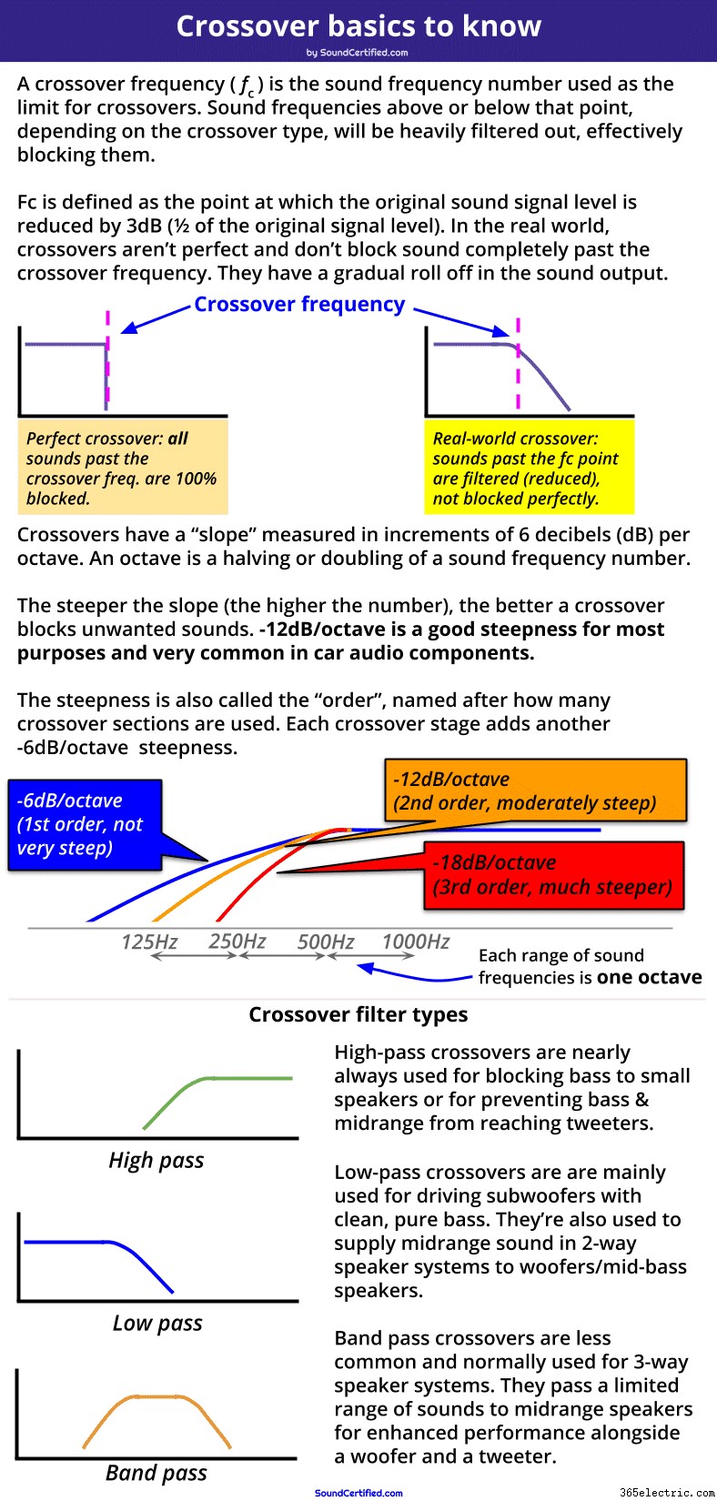
Questo diagramma mostra esempi dei 3 principali tipi di filtro utilizzati nei crossover. Sono inoltre mostrate le pendenze di crossover più comuni che è la "ripidezza" del filtro (l'efficacia con cui bloccano le frequenze oltre la frequenza di crossover).
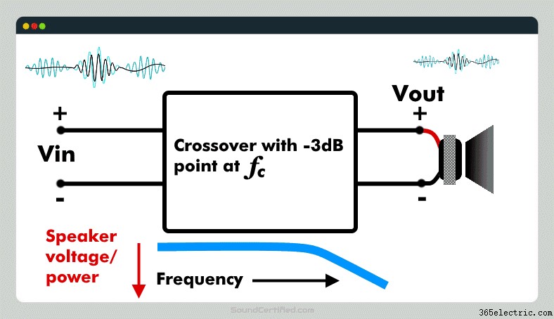
Una frequenza di crossover, comunemente scritta come Fc , è il punto di frequenza audio in Hertz (Hz) in cui il crossover fornisce -3dB (1/2) di potenza in uscita all'altoparlante. Fc è il punto di marcatura dopo il quale le frequenze sonore verranno notevolmente ridotte per impedire che raggiungano un altoparlante.
Oltre il punto di frequenza di crossover (Fc), la potenza in uscita dal crossover diminuirà sempre di più, con sempre meno potenza inviata all'altoparlante. In effetti, a Fc la tensione in uscita al carico (altoparlante) è 0,707 x la tensione di ingresso, il che significa che puoi calcolare la caduta di decibel in base alla tensione in uscita rispetto alla tensione in ingresso.
Perché le frequenze di crossover sono importanti
Quando si progettano i crossover degli altoparlanti, la frequenza di crossover (fc ) viene utilizzato come una sorta di linea che segna il punto in cui vogliamo iniziare a bloccare le frequenze sonore inviate a un altoparlante. Di solito si basa sulle specifiche fornite da un produttore di altoparlanti che elenca le frequenze sonore che un altoparlante può produrre con una buona risposta sonora e senza distorsioni.
Ad esempio, i tweeter non possono riprodurre note di basso dalla musica e possono persino essere danneggiati da esse. Sapendo questo, vorremmo scegliere una frequenza di crossover sufficientemente alta da bloccare le note di basso inviate ai tweeter per evitare distorsioni o danni. (In genere i tweeter hanno una frequenza di crossover di migliaia di Hertz [scritta come KiloHertz o kHz in breve] come 3,5 kHz, 5 kHz e così via – beh al di sopra della gamma di bassi e medi nella musica).
Una frequenza di crossover è talvolta chiamata anche frequenza d'angolo o frequenza di taglio poiché pensiamo in termini di come i suoni vengono "tagliati" dopo quel punto.
La frequenza di crossover Fc è molto importante per il design crossover
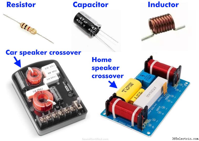
I crossover degli altoparlanti (chiamati anche "passivi" poiché non utilizzano energia elettrica per funzionare) utilizzano condensatori e induttori selezionati in base ai valori delle parti disponibili e al loro costo. Un crossover è progettato in base a una frequenza Fc iniziale e adattato secondo necessità per gli obiettivi di progettazione.
L'utilizzo della frequenza di crossover Fc come punto di partenza consente ai progettisti di sistemi di altoparlanti di calcolare i valori delle parti necessari (condensatori e induttori) a seconda dell'impedenza degli altoparlanti. Dal momento che non puoi acquistare parti di qualsiasi valore, l'FC che otteniamo in base a ciò che desideriamo è un buon punto di partenza con cui possiamo lavorare e adattarlo secondo necessità per lavorare con le parti in base alla disponibilità, al prezzo e ad altri fattori.
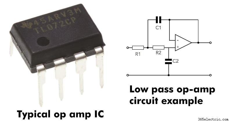
Gli amplificatori operazionali, chiamati anche amplificatori operazionali, sono l'elemento costitutivo più importante per i crossover elettronici. I crossover elettronici svolgono esattamente lo stesso lavoro (e hanno lo stesso comportamento di base) dei crossover passivi (diffusori). La differenza è che funzionano su segnali di basso livello prima vengono amplificati mentre i crossover passivi funzionano con segnali amplificati dopo l'uscita dell'amplificatore.
NOTA: In questo articolo, mentre descrivo come funzionano i crossover passivi (non elettronici, non alimentati) e le Fc, i principi sono esattamente gli stessi per i filtri elettronici.Proprio come i loro condensatori passivi più grandi o le controparti basate su induttori, i crossover basati su amplificatori operazionali hanno le stesse pendenze e il comportamento della frequenza di crossover. Lo fanno semplicemente con il segnale prima è amplificato invece che dopo di esso.
Come calcolare i decibel (dB) per la frequenza di crossover Fc
All sound frequencies after the crossover frequency are cut more and more past it with an increasingly steep reduction – to the point where they’re almost completely blocked.
In other words, a crossover filters out a range of sounds you’d like to prevent reaching speakers, starting at the crossover frequency.
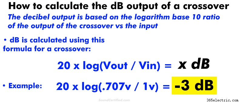
In the electrical engineering world, we traditionally use decibels (dB) when we talk about power measurements since they’re often non-linear. This just means that mathematically, power is often measured, charted, and tracked using exponential math such as logarithms (“10 to the power of x”, for example).
How crossover frequencies (Fc) and dB are related
Because crossovers reduce power at their output, it’s pretty common to measure the output reduction in decibels. One reason for this is that they have a gentle “slope” (downward curve) rather than a straight line if you were to see them graphed across the full range of audio frequencies.
For that and other reasons, we can measure the power output reduction in dB. To do so, you’ll need to know either (1) the power before and after the speaker/from the amp, or (2) the voltage at the speaker and from the amp.
Knowing those, you can easily calculate the dB output of a crossover with a scientific calculator on your computer or smartphone.
You can calculate dB for a crossover using these formulas:
- For voltage: 20 x log(Vout / Vin ) =x dB
- For power: 10 x log (Power_out / Power_in) =x dB
Understanding crossover signal level in vs out and “negative gain”
Crossover voltage out (called here “Vout”, the voltage to a speaker delivered from a crossover) can never be higher than the input – that’s not possible. Crossovers can only reduce the input directed to a speaker – they can’t amplify it. Some electronic crossovers do, but those intentionally have a gain on purpose and that’s not common in most cases.
For that reason, you’ll always get a negative dB answer if you do the math for the output of a crossover.
For the record, a negative dB value is used to show a reduction in engineering math while positive usually means a gain or increase in a signal. Amplifiers have a positive dB output (gain) while crossovers and some other components like resistors have a negative gain (a negative dB effect on a signal).
Attenuation is another way of describing a negative gain.
Nota: the gain control of an amplifier is there to compensate for a high or low input signal level and is a separate section from the crossover circuitry.How a crossover frequency Fc works:example diagram
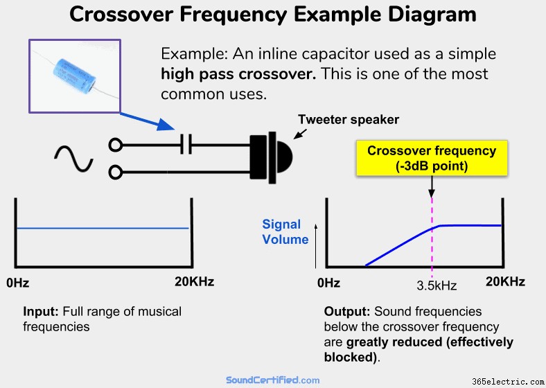
An example of a very common and simple high-pass crossover. A capacitor in series with a speaker will allow higher frequencies (above Fc) to pass with almost no volume or power drop to the speaker. It acts as a zero Ohm resistor (a short circuit wire) in series with it . However, for audio frequencies below Fc, the “resistance” (impedance, called capacitive reactance) of the capacitor will increase, allowing less and less voltage &power to reach the speaker. It will act like a very high-value resistor in series and therefore will block most of the signal from an amp sent to the speaker. In other words, a high-pass filter!
One of the problems I’ve found when we’re talking about this topic is picturing it in your mind. For example, it can be hard to understand what actually happens in real life when actually playing music in the real world vs just some explanation you’ve found on the internet.
All crossovers work the same – understand one, you understand them all (well, mostly!)
One important note I need to make is that the principles are the same regardless of the number of “orders”, or stages, a crossover has. For example, a simple 1st order crossover with a capacitor connected inline with a tweeter works on exactly the same principle as a fancier 2nd order 2-way crossover.
It’s just that the details are a little bit more complicated – not how funziona. That part never changes.
There are some crossovers with more sophisticated features &designs I won’t get into here, but for the most part, the majority are all the same and do the same thing to varying degrees. The great thing is that once you understand the basics very well, you’ve got it figured out for the most part!
The fundamentals of how crossovers work with Fc
The most important thing to know is that crossovers work by “absorbing”, or preventing, voltage and power from going to the speakers they’re connected to for the sound frequencies we don’t want them to play.
In the example from my diagram further above, you can see that:
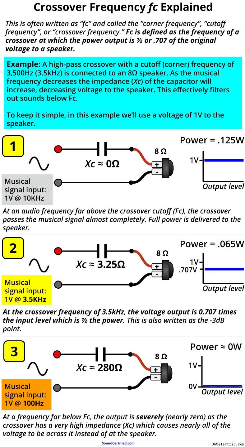
- Above the cutoff frequency Fc, a capacitor acts like an almost zero resistance connection – nothing is blocked and it acts almost like a straight section of wire.
- When audio frequencies begin to reach Fc, the impedance of the crossover goes up, acting like a high-value resistor in series with the speaker. At Fc, the speaker receives only 1/2 the power it would otherwise (which also happens to be .707 times the input voltage from the amp or stereo).
- The farther we go past the Fc limit, the crossover’s impedance is much bigger in Ohms; in fact, past a certain point, it will be several hundred Ohms typically. When that happens the speaker has about 0v and no power to it.
As you can see elsewhere in my article, the “steepness” of the drop in the power &signal level to the speaker depends on the crossover slope. A crossover’s slope is basically just a result of how many “stages”, or crossover sections, are used as needed for the particular speaker system or speakers we’re working with.
Crossovers like you see here and are always in increments of 6 decibels (dB) Per Octave:
- 1st order crossover: a single capacitor or inductor is used, -6dB per octave reduction (not very steep).
- 2nd order crossover: Two components sections are used:one capacitor, one inductor. –12dB/octave reduction (steeper, more effective, very popular).
- 3rd order: two capacitors + 1 inductor or 2 inductors + 1 capacitor are used:–18dB/octave cutoff.
..and so on, with -12db being one of the most common crossover slopes you’ll find for both car audio crossovers and home audio speakers too.
An octave is just a half or double of an audio frequency. For example, 200Hz is an octave of 100Hz, 400Hz is one octave of 200Hz, then 800Hz, and so on. Equalizers and other audio electronics may use other variations with finer numbers like 1/3 octave, for example.Crossover frequency formula math:inductive and capacitive reactance explained
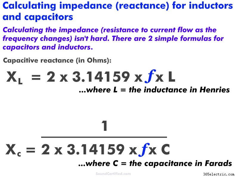
Shown here are the basic formulas for simple 1st order crossovers using capacitors and inductors. Capacitors have an impedance (Ohms) value that depends on the frequency just like inductors do.
Capacitors and inductors have a “resistance” called reactance (in Ohms just like resistance) that depends on the frequency. Here are a few basic things to understand:
- Capacitive reactance increases as the frequency DECREASES. It’s normally written as “Xc.” Capacitance is marked in units of Farads, with most capacitors being values in the microFarad (uF) range, nanoFarad (nF), or even picoFarad (pF).
- Inductive reactance INCREASES as the frequency increases. It’s normally written as “Xl.” Inductance is marked in units of Henries and typically found in units of microHenries (uH) or milliHenries (mH).
Again, it both cases, it’s just a form of impedance much like how a speaker voice coil that has a certain amount of inductance due to the coil of wire inside does. Both are measured in Ohms (Ω).
However, they complement each other and behave pretty much like the opposite of each other. Ad esempio:
- Capacitors act like high-pass filters when connected in series and low pass filters in parallel.
- Inductors act like low-pass filters when connected in series and high-pass-filters in parallel.
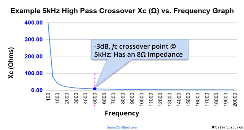
This graph shows an example of a simple high pass capacitor using a 3.98 microFarad capacitor with an 8Ω speaker with a crossover frequency (Fc) of 5kHz. At the Fc value, the impedance is the same as the speaker load (8Ω) which means the speaker power has dropped to 1/2. Further below Fc the impedance grows higher and higher, blocking bass frequencies more and more.
More great crossover and audio articles you’ll love
Don’t miss out on these fantastic articles just waiting for you to read &enjoy!
- Level up your audio knowledge in less than 10 minutes! Learn a ton of details about how crossovers work in this highly detailed article.
- What happens if you use a different speaker impedance with a crossover? It does make a difference, in fact!
- Want better sound from your car or home system? Find out what crossover frequencies to use here.
Need help? Don’t be shy! :)
Got comments, questions, or concerns? Friendly comments and requests for help are always welcome! Just drop a comment below or reach out via my Contact page here.
Thanks!